The simple explanation that describes the function of an exterior wall assembly is that it separates the exterior environment from the interior environment. To perform this “simple function” the assembly must control heat flow, control air flow, control water vapor flow, control rain penetration, control light, solar and other radiation, control noise, control fire, provide strength and rigidity, be durable, be aesthetically pleasing, and be economical. As you can see this simple function got complicated in a hurry as Mr. Hutcheon pointed out in 1963 in an addition of the Canadian Building Digest. Below we will discuss two of the functions, controlling water vapor flow and rain penetration, to increase long-term durability of the wall assembly via a drained and ventilated rainscreen.
Although the term “rainscreen” is well known in the North American construction industry, there are variations of the components in the system as well as the function of those components. The recently formed Rainscreen Association in North America defines a rainscreen as, “An assembly applied to an exterior wall that consists of, at minimum, an outer/inner layer, and a cavity between them sufficient for the passive removal of liquid water and water vapor” (Figure 1).
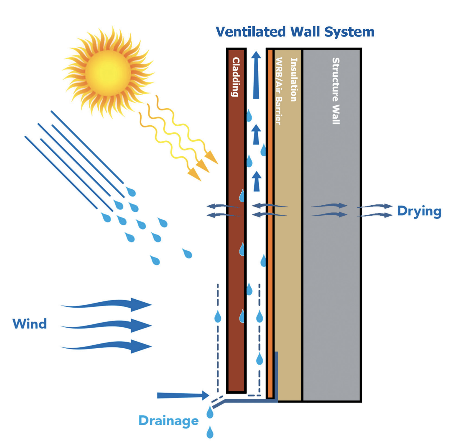
Figure 1: The air cavity – draining and venting
Source: Vented cladding assemblies prevent reverse vapor drive and allow vapor-permeable water-resistive and air barrier (WRB/AB) Membranes to Enhance Wall Assembly Drying Vented Cladding Assemblies Prevent Reverse Vapor Drive and Allow Vapor-Permeable Water-Resistive and Air Barrier (WRB/AB) Membranes To Enhance Wall Assembly Drying (vaproshield.com)
Components of a Rainscreen Wall Assembly
The first component of any rainscreen will always be the cladding (outer layer) Figure 2. Cladding can be defined as any material that forms the exterior finish of the wall assembly and functions as the first plane of protection (water shedding surface). As cladding is unprotected from the elements (UV exposure and precipitation) , it is defined as a wear layer that will require replacement at some point in time over the life span of the building. Cladding is often a non-structural component of the wall assembly; however, claddings are subject to various loads such as structural (gravity, wind, seismic, creep, deflection…etc.), environmental (driving rain, snow, ice, temperature…etc.), combustion (flame spread, smoke, fuel loading…etc.) that should be accounted for during the design phase. The number of joint treatments (open, closed, baffled…etc.), flashings, trims, and other accessories will determine the water penetration rate into the wall assembly and the corresponding load on the materials inboard of the cladding.
The second component is the physical gap between the rear face of the exterior cladding and the front face of the water control layer and/or exterior insulation. This gap has several important functions that it must provide such as a capillary break, a drainage plane, a ventilation channel, and a pressure equalizer for the cladding. Throughout North America the depth of the gap varies; however, it should be large enough to break the surface tension of water between two materials, allow liquid water to drain via gravity, and promote air movement that allows the cavity and cladding to dry (Figure 2).
The third component could be a mechanically fastened membrane, peel and stick membrane, a liquid applied membrane, or an exterior insulation with seal joints functioning as the water control layer (another term commonly used water resistive barrier – WRB) Figure 2. The location of the water control layer can vary slightly depending on the design of the wall assembly, but the water control layer should always be located inboard of the drained gap. The water control layer should be continuous, any penetrations should be sealed, and all openings should be flashed to drain out and away from the building.
The final component is the wall structure (Figure 2). There are several different materials that can comprise the wall structure, but ultimately this component or components provide the structural support for the cladding attachment and the substrate for the water control layer.
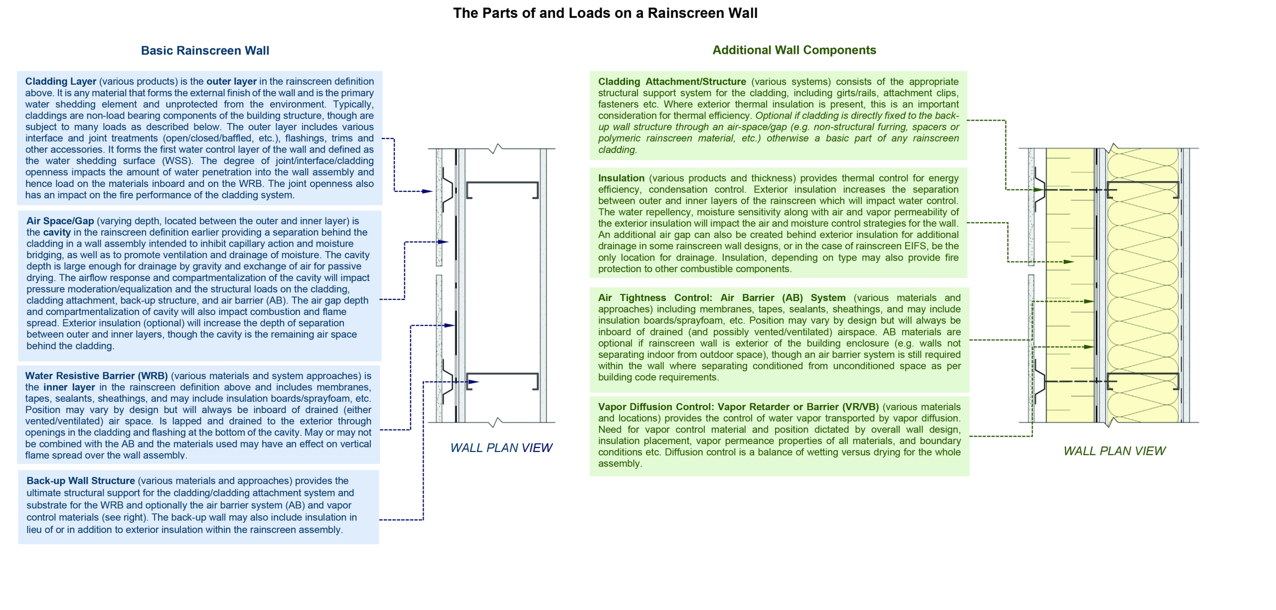
Figure 2: Basic rainscreen wall & additional wall components
Source: RAiNA - D-188-001-rev-0-RAiNA-Technical-Bulletin-Defining-Rainscreen-Wall-Performance-1.pdf (rainscreenassociation.org)
Benefits of a Ventilated Rainscreen
Drainage & capillary break
It’s a common misconception that the cladding shields the wall assembly 100% from a rain event. There is a percentage of the water that will by-pass the cladding and as a result a drainage path should be provided to prevent moisture accumulation and the corresponding resulting damage. To allow drainage in behind the cladding a physical gap must be present from the backside of the cladding to the front face of the water control layer and/or exterior insulation. How big does the gap have to be to allow drainage? John Straube, PhD in the research report, “Modeled and measured drainage, storage, and drying behind cladding systems: concluded a minimum gap size of 1/32 inch (1mm) provides sufficient drainage. To break capillary tension (rise or suction) a slightly larger gap is required at an 1/8 inch (3mm). This size of gap prevents capillary suction between building components, uncoupling the cladding from the water control layer and/or exterior insulation and allows free drainage”.
Ventilation
As water is drained behind the cladding via a gap, a portion of the water could remain within the rainscreen cavity, adhering to a materials surface via tension and/or absorbed into absorbent materials. To remove the final portion of water, dry absorbent materials, and if a vapor open water control layer is present allow vapor diffusion drying towards the exterior a ventilated air gap is required. It is critical the air gap remains continuous behind the entire height of the cladding as well as remains open at the base and top of the cladding to ensure a continuous flow of air behind the cladding. There are two mechanisms that will induce air flow behind the cladding that include wind and/or buoyancy due to convection or stack-effect. Wind-induced airflow ventilation is extremely variable due to the direction of the wind, building configuration, and the vicinity of other buildings, vegetation, or the topography. On the other hand, buoyancy-induced ventilation is contingent on the air temperature differences between the air gap and the exterior environment. Moisture content also plays a factor in buoyancy-induced venting, but only when cavity vapor pressures are significantly higher than exterior vapor pressures, more on this below when we touch on limiting reverse vapor drives.
As mentioned, to induce drainage a 1/32 inch (1mm) gap is sufficient. To induce air flow a larger gap is required (Figure 3). In the research report, “Drying capabilities of wood frame walls with siding”, the researchers concluded an air flow rate of as little as 15 air changes per hour (ACH) provided enough ventilation to dry the wall cavity. Further research has indicated to provide a decent amount of air flow a minimum of a ½ inch (12.7mm) gap is required, while optimum levels of air flow behind the cladding occur when a ¾ inch (19mm) gap is provided.

Rainscreen wall examples
Source: RAiNA - D-188-001-rev-0-RAiNA-Technical-Bulletin-Defining-Rainscreen-Wall-Performance-1.pdf (rainscreenassociation.org)
Limiting reverse vapor drive
Claddings that absorb water can be problematic in directing water back towards the wall assembly. This occurs when the sun heats the exterior face of the cladding, which causes an increase in the vapor pressure between the exterior and interior face of the cladding. If the cladding is in contact with the water control layer and/or the exterior insulation the moisture can be driven back towards the interior of the wall assembly. There are two ways to combat this intrusion of moisture. The first option would be to select a low permeance water control layer and/or exterior insulation (note this option would limit the drying potential of the wall assembly towards the exterior). The second option as identified in the research report, “In search of a wall for all seasons: controlling sun-driven moisture” the authors noted, “From the experiments, it was found that vented air spaces were very effective at reducing the amount of moisture entering the wall due to solar heating. Natural stack action that occurs when the wall is heated, and the air is humidified is a passive way of controlling sun-driven moisture. While various cavity widths were briefly investigated, it appears that by providing a 1 inch (25mm) vented cavity, sun-driven moisture can be controlled.
Conclusion
As indicated by Figure 4, the configuration of a rainscreen depends on the components and the make-up of the structure. To have a functioning rainscreen a gap must be present from the rear face of the cladding to the front face of the water control layer and/or exterior insulation. To allow liquid water to drain the gap size must be at least 1/32 inch (1mm), to break the capillary action the minimum gap size must be 1/8 inch (3mm), if air movement is required behind the cladding the minimum gap must be ¾ inch (19mm), and to limit a reverse vapor drive the gap must be at least 1 inch (25mm). From a building science standpoint, it is beneficial to have all four-mechanisms functioning to ensure the long-term durability of the wall assembly. Therefore, the minimum gap in a rainscreen should be 1 inch (25mm).


