In a previous Logix Brands blog post “Transition Details at Grade” were reviewed and one finding was that failures often don’t occur in the field of a wall, roof or the foundation, but rather at the transition from one control layer or material to another control layer or material (i.e. air control layer from the roof to wall connection). For more detail on the four control layers in a building envelope, click here.
The lack of continuity could allow liquid water, air, heat loss or gain, or water vapor into the building enclosure depending on which control layer is discontinuous, which could lead to deterioration of building components or possible health issues for building occupants.
The responsibility for transition details is really a team effort that requires the corporation of three professionals, the architect, contractor/installer, and the materials manufacturer.
Two Examples of Effective Wall to Roof (Sloped and Flat) Transitions with Wall Assemblies Using Engineered Insulation Products from Logix Brands
1) A sloped roof connecting to a wall assembly.
This is perhaps the most common roof to wall transition.
In this configuration, if the attic space is unconditioned than the control layers may be discontinuous from the roof to wall interface. If the attic space is condition than the control layers should be continuous from the roof to wall interface.
As mentioned above, four control layers should be clearly detailed in the construction drawings and reviewed with the installation contractor to ensure correct implementation on site (Figure 1).
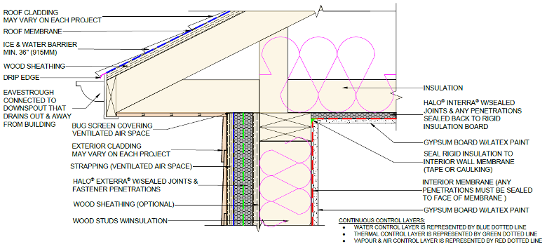
Figure 1: Sloped Roof to Wall Transition Connection of the Four Control Layers (Water, Air, Thermal, Vapour)
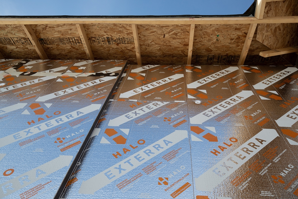
Halo® Exterra® functions as the water control layer for the wall assembly when joints of the foam insulation boards are sealed (taped or caulked) and any fasteners that break the surface of the lamination is sealed as well (Figure 1).
Two additional options for the water control layer would be:
- The implementation of a sheet applied membrane on top or behind Halo® Exterra®.
- And for the roof assembly a combination of the ice and water barrier and roof membrane (i.e. roof felt or peel and stick membrane) can function as the water control layer.
If the attic space is not conditioned the water control layer from the roof to the wall will be discontinuous as opposed to a condition attic space that would feature a continuous water control layer from the roof to wall connection.
The next most important control layer in this transition detail is the air control layer. In the example in Figure 1 the air control layer has been detailed on the interior side of the wall assembly with a sheet applied membrane. Any penetrations through this layer must be sealed with tape or caulking to ensure the control layer remains continuous.
On the underside of the attic ceiling Halo® Interra® has been illustrated. Not only does this product provide a continuous layer of thermal resistance the facer can also function as the air control layer. Therefore, any penetrations through this layer must be sealed to ensure a continuous air control layer.
The attic ceiling and interior wall air control layers can be connected with tape or caulking where the two materials intersect at the top of wall to ceiling connection.
The two materials that function as the air control layer also have material properties that allow the products to function as the vapor control layer. The wall membrane is often a version of 6 mil. polyethylene (vapor closed), however, there is a growing trend to adopt the best practice of a variable vapor permeance membrane that allows the wall assembly to dry towards the interior, while limiting moisture that tries to enter.
Halo® Interra® has a vapor permeance value of 1.7 ng/Pa•s•m2 (0.03 perms) which satisfies the requirements in the NBC and IRC respectively to function as a vapor control layer. Often, when the wall air control layer is positioned on the interior of the building enclosure the air and vapour control layers are combined into a single material.
There are two thermal control layers in the transition from the roof to wall interface. Insulation in the attic floor/between the studs (non-continuous) and the layer of Halo® Exterra® on the exterior of the building enclosure (continuous).
The Halo® Interra® is continuous on the underside of the attic ceiling expect to structural framing members at the perimeter of the wall assembly. Insulation in the attic floor and between the studs could be anyone of the following or a combination of, mineral fiber, cellulose, and spray foam.
It has been well documented in many research reports the benefits of continuous exterior insulation and how it outperforms insulation between framing members via a higher effective thermal resistance.
In addition to providing a higher thermal resistance, exterior insulation also serves to move the DEW point out and away from sensitive materials in the building enclosure (i.e. moisture formation between framing members) and wrapping the building in a continuous layer of insulation is similar to a human wearing a winter coat during cold weather, which leads to improved occupant comfort.
Joe Lstiburek summarizes this point, “If you want to stay warm, you wear your sweater on the outside. You don’t eat it. Likewise with buildings”.
2) A flat roof to wall transition.
This transition is becoming more common in residential construction.
Flat roofs are more complex than sloped roofs to ensure adequate rainwater management.
There are many versions of flat roof configurations, however, the inverted assembly offers the optimal opportunity for long term success. In an inverted assembly the membrane (water control layer, could also function as the air control layer) is protected beneath the roof continuous insulation.
This water control layer should than be lapped in behind the parapet water control layer (peel and stick membrane or liquid applied membrane) and an overlap of 6” (150MM) at minimum should occur. The parapet water control layer should then overlap the wall water control layer, in the case of Figure 2 Halo® Exterra® with sealed joints and fastener penetrations, a minimum of 6” (150MM).
The air control layer could be positioned on the exterior, however, for the example in Figure 2 this control layer has been positioned on the interior of the building enclosure.
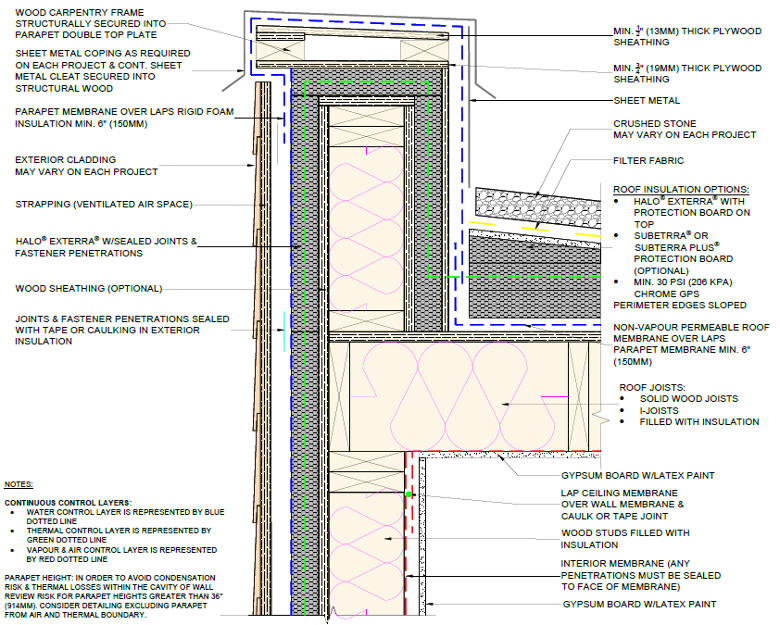
Figure 2: Flat Roof to Wall Transition Connection of the Four Control Layers (Water, Air, Thermal, Vapour)
The ceiling membrane should overlap the wall membrane by a minimum of 4” (102MM) and be sealed with tape or caulking to maintain continuity of the air control layer from the roof to wall assembly. Again, any penetrations through this layer must be sealed in order to achieve a continuous air control layer, which is mandated by the NBC and IRC.
As in the example noted for Figure 1, the air control layer/material can also function as the vapor control layer. However, a major difference is the selection of the interior membrane that is applied to the interior of the flat roof assembly.
The exterior membrane on the flat roof assembly is vapor closed, which means the assembly can’t dry towards the exterior. If 6 mil. polyethene was placed on the interior of the flat roof drying wouldn’t be able to occur towards the interior either.
Good building science practice dictates assemblies should dry in both directions and at the very least one direction.
Based on this principal the 6 mil. polyethene could be avoided and instead a variable permeance membrane could instead be selected that allows drying towards the interior. Moisture that is transferred from the flat roof assembly to the interior of the building can then be dealt with via the mechanical systems to ensure a build up of moisture does not occur.
For thermal control insulation can be placed between wall and roof framing members, but similarly to what was noted for Figure 1 it makes more sense to place insulation outboard of the structure and wrap the building enclosure in a continuous layer of insulation.
Often insulation is omitted from the parapet, which represents a thermal bridge and an area of significant heat loss (Figure 3).
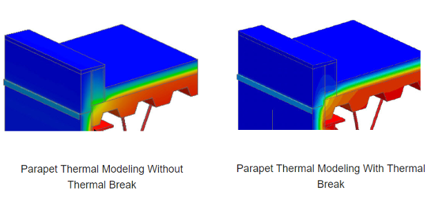
Figure 3: Parapet Roof Penetration Thermal Bridging
To avoid this negative effect the parapet should be wrapped with insulation and the insulation should connect to the wall and flat roof continuous insulation.
If there’s one thing to take away from this article its to ensure construction drawings and site construction feature the four control layers (water, air, thermal, and vapour) and if possible and when it makes sense ensure these control layers are continuous.
If you aren’t sure how a control layer should be detailed or implemented on site, please reach out to Logix Brands we are always happy to help!
(Figure 3 Source: Parapet Penetration | Thermal Bridging Solution | Armatherm)


